iRobot Roomba Bumper Sensor repair

Roomba 9-beep error fix
Fixing iRobot Roomba 5xx, 6xx circle dance
iRobot Roomba is broken? Does it ‘circle dance’ and plays the 9-beep error?
This guide will show you how did I fix my iRobot Roomba 560 bumper sensor.
לפוסט בעברית על תקלת 9 ביפים, כשל בסנסור הפגוש ומה לעשות כשמופיעה, לחצו על הקישור
My Roomba 560 stopped working normally, started to ‘circle dance’ and played the 9 beep error.
This means: “the robot is stuck with its bumper pressed in, or the bumper sensor is dirty”. It may also suggest that the sensor’s IR emitter is dim / weak or dead.
In order to fix it, we need to open Roomba, get to the sensor and find out if it is dirty or faulty and if needed, replace the emitter.
This post shows the fix to my 560. As far as I understand it is the same for all Roomba 5XX and some 6xx models.
This fix is ONLY for those with electronics and mechanical knowledge and skills.
DISCLAIMER - Important!
Especially I would like to thank Dajiu who gave me his permission to use some of his photos. Dajiu BTW has an excellent page on Roomba 550/5xx Cliff Sensor fix
1. Verify that the Clean LED is Off
2. Press and Hold both the Dock and Clean Buttons.
3. Press the Spot Button 6 times
4. Release the Dock and Clean Buttons
Roomba will enter test-0 and play a sequence of tunes and then begin to flash all the LEDs on the faceplate.
In order to advance to the next test, press the Dock button once.
We need to get to test-2, so click the Dock button twice.
Upon entering the bumper test, Dirt Detect led flashed blue and the Clean LED will turn on Red. The program waits for the user to press the left side of the front bumper. This will light up the Spot LED until the bumper is released.
Next press the right side of the front bumper and the Dock LED will turn on and stay on until the bumper is released.
Once that action is accomplished, the Clean LED remains Red.
If any of the above will leave its Spot / Dock led’s ON after you released the bumper side, it means this side has fault in its sensor.
Push both DOCK and SPOT for 10 seconds to exit test mode
![]() Note:
Note:
Bumper sensors are assembled in a kind of ‘sealed’ housing and there is no way to look at it from the outside with a digital camera/smartphone in order to determine/confirm that the sensor is fault, so let’s start digging in.
Needed components and tools:
Here is a list of 4 possible pairs of right angle through-hole components reported to comply with the 5xx. Each component # links to its data-sheet.
It is important to note that the following component set are through-hole (thru-hole) components. This means the components has leads to be inserted into holes drilled in the printed circuit boards (PCB). Those leads are soldered to pads on the opposite side of the PCB.
iRobot designed this PCB to stand massive vibrations and impact that this sensor is experiencing during normal Roomba work. It is strongly recommended to keep the original design and use through-hole IR components to maintain this robust design.
* Other components might also work. If you consider using other components,
it is advised to compare their electric and mechanical characteristics to those listed here.
You will also need soldering tools such as: Solder iron, Solder Flux, De-solder pump etc.
1 |
2 (optional) |
| IR Emitter (Tx) | IR Photo-Transistor (Rx) Reported not changing characteristics/get fault. Still, you might consider replacing it as well due to matching heights. |
| LiteON LTE-302 this component is Clear with Yellow paint on its top face |
LiteON LTR-301 this component is Clear with Pink/Red paint on its top face |
| Fairchild QEE113 this component is Clear with NO paint on its top face |
Fairchild QSE113E3R0 this component is Black with Blue paint on its top face |
| Everlight EL-IR928-6C | Everlight EL-PT928-6C |
| Optek OP-140A | Optek OP-550A |
|
And where do I buy it? Cost of IR pair is ~US$1.0-1.95 (Mar.2010), a lot less than sensors kit offered by some stores/sellers. |
|
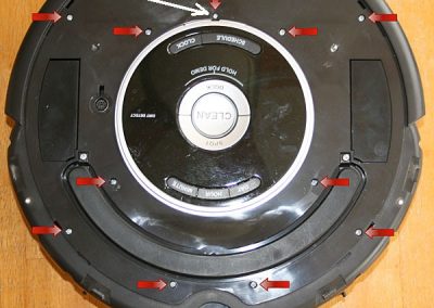
Lift up the silver/else decorative cover. The plate is held with snaps, start the lift in the bin area and move further from there. Press on the snaps with a screwdriver to release them if needed. When you reach the handle area, lift the handle and take the plate out in a diagonal movement.
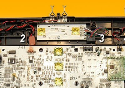
Unscrew the 2 screws holding each sensor to the chassis
and move just a bit the fault sensor module.
in order to fix the sensor, you can work locally or remove the sensors kit out
( this kit also share the cliff sensors and wires ) .
if you do so, make a drawing of the wires so you’ll know how to assemble it.
I recommend working locally on each sensor and avoid the hassle.
Slide the rubber cap of the sensor first to make a way for the cover removal.
Cover is attached with snaps, be very careful not to break it, use a wide thin flat screwdriver that you place under the snap loop and twist the screwdriver gently, just a bit to release the snap.
Now is the stage where you can check:
A. if the inside is dirty (which I doubt),
clean if necessary and assemble to test again.
B. check the solder points of PCB components.
I got report of bad solder points that caused malfunction of IR components.
To test the emitter, connect power and look at the emitter with a digital camera
or a smartphone to see if the emitter is working / dim.
Most digital cameras and nowadays smartphones are able to see and show IR light
If emitter is dim / not working, go on to IR parts replacement.
After you removed the sensor cover, release and remove the lever spring. Pull straight up the lever together with the IR PCB, than separate it.
![]() Pay attention to lever’s metal hinge, it should go to same location when assembling.
Pay attention to lever’s metal hinge, it should go to same location when assembling.
If you are not a mechanical skilled person, I recommend you to make a photo/sketch of this assembly so you’ll know how to assemble it later.
Decide if you are going to replace emitter only or both emitter-photo transistor.
Note: Before you replace any component, check solder points, see section 14B above.
If you find any bad solder point, renew it and test.
Check the difference of lens’s center height between fault component and replacement part,
You need to match the height so the replacement emitter will be facing the receiver one and both lenses with same height.
![]() Pay attention:
Pay attention:
a. Emitter is the component far from the wires !
Photo transistor is near the wires and has Blue color on top (iRobot part)
b. Both emitter/photo transistor has a small half-sphere lens on its front surface.
Lenses should face one to each other !
While you are here, decide if you want to replace the 2nd sensor IR components as well
or wait to your Roomba’s next 9 beep…
iRobot used such an ‘excellent quality’ components that Murphy is probably waiting for you.
Avi’s advise is to replace both and forget from this fault for at least another year ![]()
You may stop after assemble the main PCB and apply power to check your fix or complete it and than do the check.
If you have completed the assembly and left without any screw, hit the Clean button and see if your Roomba is dancing its normal dance again…
Did you find this article helpful?
Did it save you time and trouble?
If yes, please consider donating some $$$ to help me cover the hosting cost involved. Thanks
To make a donation, please click the following PayPal button:
Have fun and enjoy your Roomba ![]()
Comments, remarks and updates are welcome.
Some will be published, with hidden sender's details.
iRobot Roomba DIY Guides by Avi
9-beep fix | power-supply conversion | speaker fix
5xx-7xx CHM cleaning | 8xx-9xx CHM cleaning
Red CHM mod | Gray CHM mod | battery rebuild
Here are some testimonials that I have received:
– N.S. from USA:
Hi Avi, I really wanted to thank you for taking the time to put together such an excellent instructional page.
The combination of the detailed photos, great verbal instructions, links to parts with data sheets and manufacturers part numbers, all combine to make your instructions as good as they can possibly be!!
Keep up the great work!
– R.P. from USA:
Thanks for the page! I fixed mine in about 2.5 hours for a couple bucks and didn’t have to deal with iRobot’s incredibly poor customer service.
– L.Z. from USA:
Really neat work you posted online! Saved my Roomba based on your instruction of changing IR emitter
– D.L. from Canada:
Thank you Avi for this great detailed guide. After failing with a non-solder, gluing fix that lasted few cycles only, I re-fixed my Roomba with thru-hole components and it seems as a much better and reliable repair.
Thank you for the effort.
– N.S. from USA:
Your pictures of the Roomba and the detailed descriptions were perfect! I bought the parts from Mouser, soldered them at work (where we have a nice electronics lab), and it is working marvelously! You saved me a lot of money. Keep up the great work!
– E.L. from USA:
Your Roomba fix is excellent and worked as expected. Saved us a lot of money. Thanks!!!
– S.J. from USA:
Outstanding instructions!
With your help, I was able to revive my $300 door stop to a fully functioning Roomba 560…
Copyright © Schneor Design. All rights reserved. Do not copy without written consent from the author.


Hi dear this roomba ir led and transiztor What part number does it use
Hello Deniz
Please read carefully part B. that lists some possible alternatives and has links to each alternative data sheet.
Good luck
Great guide to complete the fix. I think that if this guide is not clear to readers they should not attempt the fix. Thanks again, as I had an erratic receiver and a dim transmitter. Drove me crazy. All good now. Keep up the good work.
Avi,
Great info layout. One question, how to power the sensors IR components when disassembled?
Thanks,
Joe
Thanks Joe
You can test IR led and photo diodes with and without a multimeter.
Google it and you’ll find guides on this.
Good luck
Dear Avi, thank you so much for your instructions. They are clear and simple.
I did the tests and I had no answers from my Roomba. I am planning to buy all thru-hole components before open the Roomba, and I wonder if you could inform how many pieces of each part number a Roomba typically has.
I wish you the best,
Antonio
Thank you Antonio
Each sensor has one of each and since there are 2 sensors you’ll need two (2x) of each type.
Good luck
Avi