DIY Nikon F100 Interface cable by Avi

by Updated: Nov 11, 2020diy-photography0 comments

Nikon F100

Interface cable build by Avi

DISCLAIMER – Important!

First task was to understand the F100’s 10 pin connector and get a 10 pin plug.
This connector is a custom one and I couldn’t find any second source for it.
Some newsgroups posts and sites suggested various ways of how to build your own plug
based on a PS2 plug or making a mold over pins for example. Seeing those fragile and insecure
solutions I thought this is too risky and decided to use an original Nikon plug.
I purchased a used MC-22 cable, split it and used the original Nikon 10 pin plug and cable.
(you can probably do the same with any other Nikon cable that has a 10 pin plug)
I started by mapping the F100 receptacle (on camera) and plug (MC-22)
Please note that Nikon located the connector on the camera rotated, as soon as I realized that I should place a “virtual” axes on the images (and in my mind), it became very clear and readable.
My guess is that Nikon placed the camera connector that way because the designers wanted to use an existing plug and this orientation was best from ergonomic point of view of the F100 and its flash socket. Well, we got a plug that fits several cameras, but we also got a strange orientation and not so convenient usability of it as well.
So, one axis was placed over the 2 recess on connector sides (that accepts the small guide ribs of the plug) and the other axis was placed over the top recess that also accepts a mating rib of the plug.
thumbUP_gifanim Tip : Your job will become easier if you’ll refer to the pins arrangement as to 4 slices of a circle !  Each slice has 2 pins in it and 2 pins are in the center.

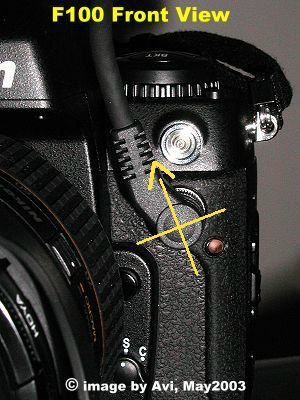
Here are the mapping of pins and wires colors.
Both images are FRONT view and represent real orientation of connector and plug.

And now from theory to practice. I soldered all 10 wires of the plug to the DB-15 connector in the same order mapped (pin #1 of MC-22 to pin #1 of DB-15 …) so I know exactly where is each wire on the interface connector. Connecting all 10 wires assures that I’ll be able to connect to any combination of pins for any future accessory I might want to add.

Avi’s Nikon F100 cables project posts:

My concept | DIY Interface cable | DIY DataCable-1 | DIY DataCable-2
DIY MC-30BUY DataCable2

Comments, remarks and updates are welcome.
Some will be published, with hidden sender's details.

Did you find this article helpful?
Did it save you time and trouble?
If yes, please consider donating some $$$ to help me cover the hosting cost involved. Thanks

To make a donation, please click the following PayPal button:

Copyright © Schneor Design. All rights reserved. Do not copy without written consent from the author.

0 Comments

Submit a Comment

Your email address will not be published. Required fields are marked *

electric hazard sign

Disclaimer

1. Nikon cameras contains electronics.

Any modification made to your Nikon camera may cause damage to your equipment and harm to yourself or to others. 
Any modification made to your Nikon cameras AND/OR to a 3rd party attached accessories will void manufacturer warranty.
None of the following steps is recommended by me nor by the manufacturer, Nikon. 
This post show only my personal experience and know-how.
If you follow any of the steps, you do it on your own risk and responsibility.

2. Copyright © 2003 Avi. All rights reserved. 

Content including all text and images in part or in whole may not be reproduced, retransmitted, stored, distributed, disseminated, sold, published, broadcast or circulated in any medium
without written consent of the author

You have Successfully Subscribed!

Pin It on Pinterest

Skip to content